Ok, the long awaited finale in the pull up bar series. Thus far, I’ve covered: materials, tools, anchoring and design – now it’s time to walk you through construction.
You probably this guessed already but, the construction process is unique for every system due to the snowflake like nature of each design. So, to realistically discuss the construction process, I’m going to walk you through the build out of the original CrossFit 626 garage bar.

A write-up like this isn’t the greatest medium for conveying this information, so bear with me. If you have any questions or need clarification on anything, let me know in the comments below. Next time I build one of these rigs, I’ll be sure to make a video. Anyway, here we go.
Plans
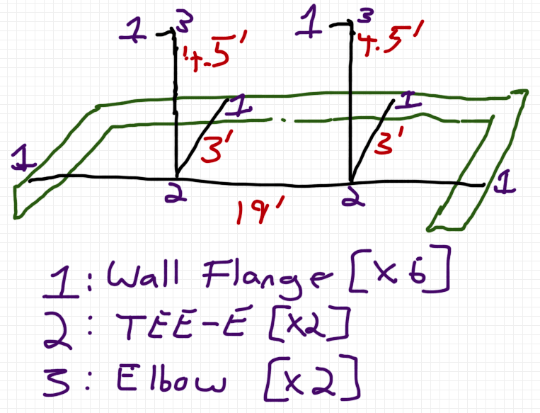
By now you should have a sketch of the system you’re going to build, all the materials and tools needed to complete the project and an idea of how it will all be anchored. Unfortunately, I don’t have the original sketch of the example system I’m going to walk you through constructing, but I’ve include a simple recreation below. Pipe lengths are depicted with the red numbering, speed rail fittings are depicted with the purple numbering and the orange lettering will be used as reference points as I walk you through construction.

Pull Up Bar Plans
For my example system, my main bar is 19 feet in length and is anchored to the wall on either side (Point A) with wall flanges and to the ceiling (Point C) and back wall (Point B) through the use of support pipes. The thickness of the ceiling joists allows me to directly bolt the fittings into them, but the 2×4 construction of the perimeter walls requires that I install additional support structure for mounting at points A and B. I opted to install a 2×10 board around the perimeter of the pull up bar for ease of mounting (shown in green in the plans above).
Support Structure
The first construction step was to install the 2×10 support structure. The boards were affixed to the existing 2×4 walls with lag screws. The 2×4 studs were spaced by 16″ and I elected to put 1 lag screw into each stud – alternating position on the 2×10 (bottom and top) which you can see in the picture below.

Lag Screws Alternating High and Low Positions in the 2×10 Support Structure
The 2×10 support structure was install all along the back wall of the pull up system for the point B mounts and then along the sides for the point A mounts – again, this is shown in green on the plans above.
Piping
 With the 2x10s in place, I moved onto the piping. When working with the piping, I like to make my cuts as I go along. In theory you should be able to cut everything in advance and throw it all together, unfortunately, it rarely works that way.
I began by cutting the long 19′ section that spans between the two orange “A” letters in the plans. Then I measured 3 feet out from the back wall (and 7.5′ from the ground) to mark the center position for the wall flange. Holding the flange up to this position, I then marked the four mounting holes on the 2×10. Prior to installing the wall flange, I highly recommend pre-drilling these marked mounting holes, this will cut down on splits in your support structure. This process was repeated for both “A” wall mount flanges in the plans.

Next, I slid the two TEE-E fittings on the pipe for the connecting support piping (purple 2s in the plans), then the two wall mount flanges on either end (purple 1s) and hoisted the 19 foot section of pipe up. I aligned the wall flanges with the predrilled holes and used a ratchet to affix the flanges to the wall with lag screws. You will need a partner for this (and a level). Once the two wall flanges are in place, you can tighten down their set screws with an Allen wrench to lock the pipe in place and keep it from rotating or shifting.
With the main pipe in place, it was time to install the support pipes. I started by cutting the two 4.5 foot sections of pipe that are used to mount into the ceiling rafters. These are installed one at a time. You can see the details of how I accomplished my mounting into the rafters in the picture below. Again, all mounting holes for the flanges were pre-drilled prior to installing the lag screws.

You want to make sure that the pipe going from point C to point D is the proper length. Too short and it won’t seat well into the TEE-E fitting at point D, too long and it will force the 19 foot section of pipe to bend downwards. No shortcuts here, get it right. When affixing the pipe coming down vertically from the ceiling (point C) to the 19 foot horizontal section of pipe in the TEE-E (point D), make sure to get the pipe seated well in the TEE-E fitting. The last step is to tighten the set screws.
After getting both ceiling mounts in place (point C to D), I moved onto the final pieces of support piping to be installed – the two 3 foot sections that extend from the TEE-E (point D) to the back wall (point B). Following the same process as with the other piping and flanges, I mounted these last two pieces of pipe.

After all pipes and flanges are in place and installed, it’s a good idea to go back over all the speed rail fittings and ensure that the set screws are all properly tightened.
Proof Test
The final step in the construction process is the proof test. Start with a single person dead-hanging at a couple different places on the bar. Next have this person add dynamic movement, such as performing kipping pull ups.

Slowly built up the loads by adding people (that understand they’re part of a proof test). It’s always good to test with more people than you plan to have using the bar regularly. The example bar was meant to hold 6 people, so I got 8 up on it to get a good load test and build confidence that it will hold up as designed.
Completed Project

Summary
I totally understand that a text article like this isn’t the greatest way to convey construction instructions, but it’s the best I can do for now. Feel free to ask me any questions you’d like in the comments below. A project like this can be completed in a day, just make sure you’ve done all the proper prep work: procuring supplies, prepping tools, etc.
If you use these instructions to build your own rig, I’d love to hear about it too and see photos… let me know. Good luck!
[ois skin=”Garage Gym”]